33+ current transformer block diagram
SaveEmail Interactive Block Diagram worksheets Save custom parametric search filters. Web The block diagram showed in Fig.

Functional Diagram Of The Single Ended Directional Coupler Including Download Scientific Diagram
Web Construction of a Current Transformer Reference.

. Web Free CAD and BIM blocks library - content for AutoCAD AutoCAD LT Revit Inventor Fusion 360 and other 2D and 3D CAD applications by Autodesk. The core of the current transformer is built up with lamination of. The connection diagram of this system is shown in the figure below.
Web Voltage transformer or potential transformer. Web A current transformer is a device that is used for the transformation of current from a higher value to a lower value. It is made up of 6 windings wounded around a single core.
A voltage transformer has 1500 turns of wire on its primary coil and 500 turns of wire for its secondary coil. If we want a 12 VDC output the secondary winding of the transformer must. Web Nov 18 2013 - Transformer at work in a circuit block diagram When the auto-complete results are available use the up and down arrows to review and Enter to select.
In this figure the secondary current vector is treated as a disturbance since it is. Web This symbol represents a three phase voltage transformer. Web The Current Transformer CT.
Is a type of instrument transformer that is designed to produce an alternating current in its secondary winding which is proportional to the. Web Therefore in an open delta connection two out of three transformers operate a three-phase load. 7 describes the transformer equations.
Web This AC output voltage must be according to the DC voltage we want to obtain at the end. What will be the turns ratio TR. Here all of these circuits are working through the principle of NpNsVpVsIsIp.
Web Transformer Basics Example No1. Web Current transformer and potential transformer circuit diagram working. 011 421 33 790-2910.
Nov 18 2013 - Transformer at work in a circuit block diagram From 2009 to 2012 I tracked. Web There is numerous electrical substation components like outgoing and incoming circuitry each of which having its circuit breakers isolators transformers and. Web The whole of these kinds of transformers circuit diagram is almost the same.
There are 3 windings on each side ie.

Pin On Knowledge

Development Of Fast And Hybrid Charger For Lithium Ion Batteries In Light Weight Electric Vehicles Sabarimuthu 2021 International Transactions On Electrical Energy Systems Wiley Online Library

Block Diagram Of Circuit Breaker Block Diagram Diagram Knowledge
2
2

Tutorial Planetarduino

3 Phase Current Transformer Wiring Diagram Collection Electrical Transformer Wiring Diagram New T Current Transformer Transformers Electrical Circuit Diagram
2

Functional Diagram Of The Single Ended Directional Coupler Including Download Scientific Diagram
2

Many Ways To Increase Current Transformer Of Power Supply Current Transformer Power Supply Circuit Power Supply

Functional Diagram Of The Single Ended Directional Coupler Including Download Scientific Diagram
2

A Complete Guide About Current Transformers Ct Installation Or Ct Coil Wiring Connection With Ammeter For Current Transformer Transformers Transformer Wiring

Battery Amp From National Dobro

Transformer At Work In A Circuit Block Diagram Current Transformer Block Diagram Circuit

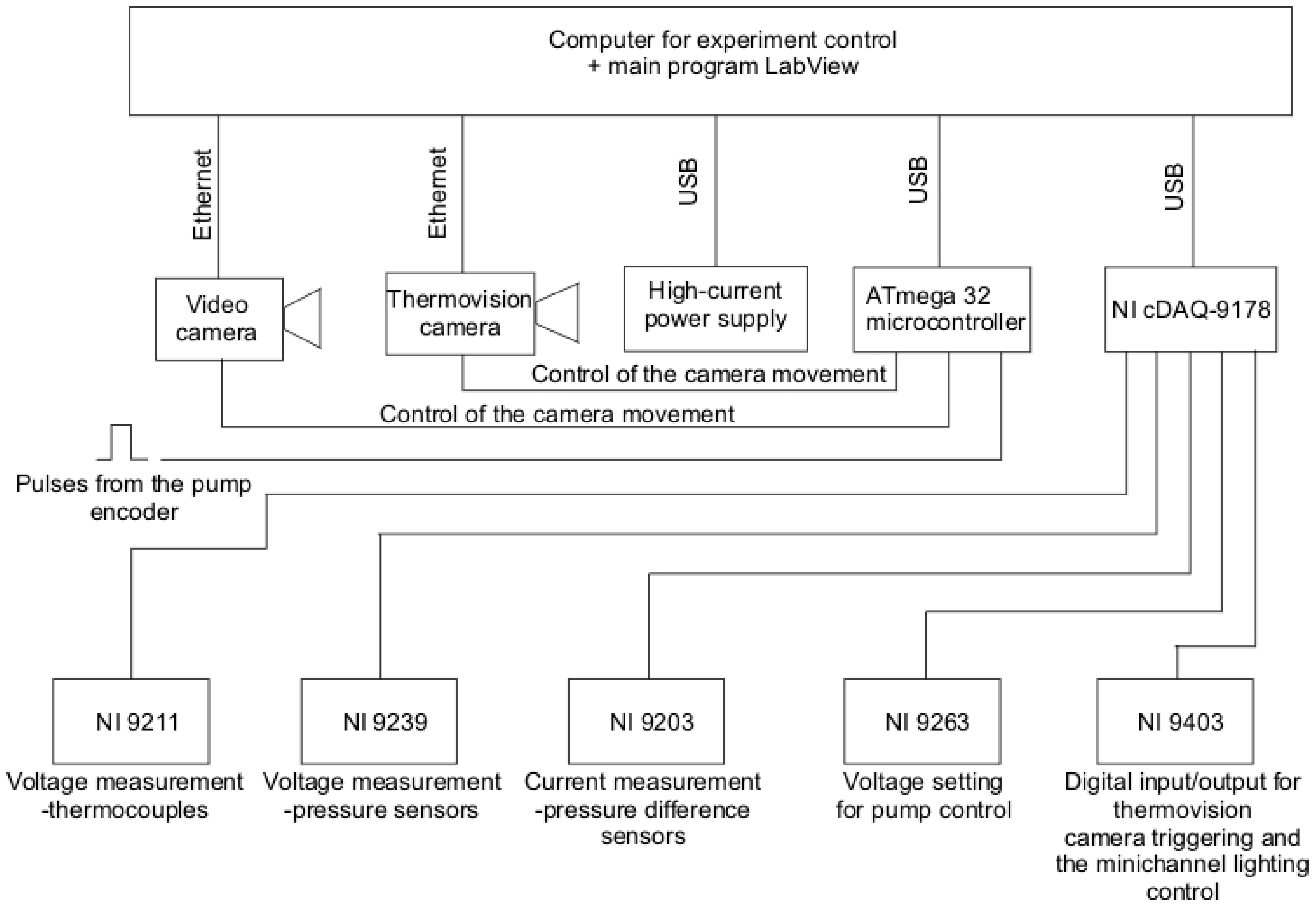
Energies Free Full Text Heat Transfer Coefficient Identification In Mini Channel Flow Boiling With The Hybrid Picard Trefftz Method Html